S0 Base Board
Modular expansion board for S0 IoT Gateway
S0 Base Board
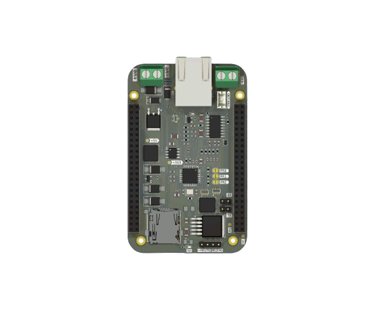
The S0 Base Board is a modular expansion board designed to power and extend the functionality of the S0 compute module. It integrates critical components for industrial IoT and smart metering applications, making it ideal for professional deployments.
Overview
The Base Board transforms the S0 module into a complete gateway solution. The S0 board acts as a cape to the Baseboard, connected via 2x23 male headers on the S0 fitting onto the female headers of the Baseboard. The Baseboard supplies both 5V and 3.3V to the S0 board.
Features
- Onboard W5500 Ethernet controller for wired Ethernet connectivity
- TSS721A transceiver for M-Bus communication
- Wired M-Bus connection via Screw Terminal (
J1) - SD Card slot for data logging
- Dual 2×23-pin vertical pin sockets (
J5,J6) for connecting the S0 board - 24V maximum input via Screw Terminal (
J2) - Battery input and onboard charging circuit via JST connector (
J3) - SPI and UART routed through
J5/J6to communicate with the S0 board - Protection components: diodes, inductors, capacitors for power and signal integrity
- Modular and expandable design with solder jumpers for configuration
Connector Overview
| Reference | Type | Description |
|---|---|---|
J2 | JST Connector | 24V DC Power Input |
J3 | JST Connector | Battery Input and Charging |
J5 | 2×23 Pin Female Header (2.54 mm) | Main S0 interface (SPI, UART) |
J6 | 2×23 Pin Female Header (2.54 mm) | Secondary interface to S0 |
JP2 | Solder Jumper | Config option for W5500 |
JP3 | Solder Jumper | Config option for W5500 |
Getting Started
Powering the Board
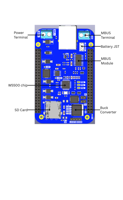
The Baseboard is powered by a 24V max DC power supply. The power supply is connected via the Power Screw Terminal with polarity as marked on the board. Reverse polarity protection and overcurrent protection are enabled for safety.
The Baseboard can also be powered by a 7.4V battery via the Battery JST connector.
Testing Power
Power supply to the board is converted to 5V and 3.3V by the Buck Converter and 3.3V Regulator. To test, connect a multimeter and measure voltage at the 5V and 3.3V test points labelled on the board.
Ethernet
The Baseboard has an onboard Ethernet port via the W5500 Chip, which supports Auto Negotiating modes configurable via solder joints on the board:
- 10 Mbps Half-Duplex
- 10 Mbps Full-Duplex
- 100 Mbps Half-Duplex
- 100 Mbps Full-Duplex
Wired M-Bus
The Wired Meter Bus is a 2-wire interface connecting to Wired Meters via the MBus Screw Terminal with markings as shown on the board.
Data Storage
The Baseboard is equipped with a MicroSD card slot for storing M-Bus data locally.
Power System
- Primary Power Input: 24V via
J2 - Battery Backup: Via
J3with charger IC circuit - Protection: Diodes for reverse polarity, inductors for EMI
- Power Output: Supplies the connected S0 board through headers
Communication Interfaces
W5500 Ethernet Controller
- Provides wired network connectivity
- Communicates with the S0 via SPI
- Auto-negotiation for 10/100 Mbps speeds
TSS721A M-Bus Transceiver
- M-Bus driver for utility metering
- Communicates with the S0 via UART
- Compatible with standard M-Bus devices
- Screw terminal wiring
SD Card
- SPI interface
- SDHC support
- FAT32 filesystem
- Local data logging
Architecture
The S0 BaseBoard serves as a cape that powers and extends the S0 module:
| Interface | Direction | Connected To |
|---|---|---|
| SPI | S0 ↔ W5500 | Network Comm |
| UART | S0 ↔ TSS721A | M-Bus Comm |
| Power | BaseBoard → S0 | 5V or Battery |
PCB Layout
- 4-layer board with copper on F.Cu and B.Cu
- Board thickness: ~1.6 mm (standard FR-4)
- Modular footprint with JST and pin headers
Use Cases
Smart Metering Installations
Perfect for utility monitoring deployments:
- Mount in apartment block electrical cabinets
- Read legacy wired M-Bus meters
- Collect wireless M-Bus data simultaneously
- Log readings to SD card for redundancy
- Backhaul via Ethernet or cellular
Industrial IoT Gateway
Ideal for factory and industrial environments:
- DIN-rail mount in control panels
- Wired Ethernet for reliability
- Battery backup for critical monitoring
- Local logging for compliance
Remote Monitoring Stations
Suitable for off-grid installations:
- 24V power from solar systems
- Battery backup for night operation
- SD card for offline data collection
- Multiple connectivity options
Building Automation
Deploy in commercial buildings:
- M-Bus for HVAC and utility meters
- Ethernet backbone connectivity
- Local data aggregation
- Centralized cloud reporting